

But loose connections act like speed bumps, restricting the flow and creating friction as well as heat. Tight connections between conductors create smooth transitions derived from one of conductor to an alternative. In fact, it is extremely normal for 20-amp general-use circuits to get wired with 15-amp receptacles.Įlectricity travels along conductors, such as wires and the metal contacts of outlets and sockets. Note, however, that there isn’t any danger to installing 15-amp receptacles in 20-amp circuits since it is perfectly fine whenever a plug-in device draws less power compared to circuit amperage.

Installing such a receptacle on a 15-amp circuit assists you to possibly overload the circuit in the event you plug this kind of 20-amp appliance into it. This shape allows 20-amp appliances, which have a matching T-shaped prong, being inserted. A receptacle rated for 20-amps carries a unique prong shape by which among the vertical slots has a T shape. This is especially important when replacing receptacles. When replacing a switch, light fixture, or outlet receptacle, be sure to not put in a device that is rated for additional amperage compared to circuit carries.
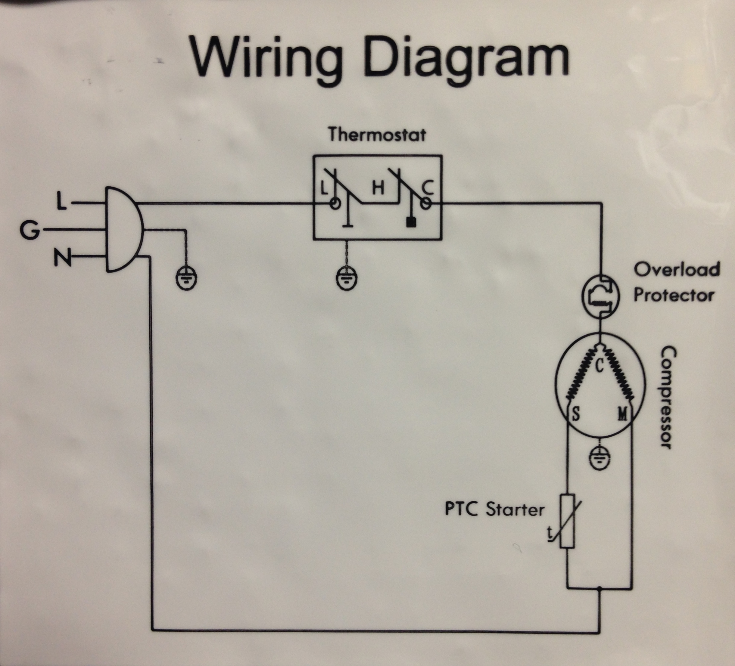
#12 VOLT AIR COMPRESSOR STARTER WIRING DIAGRAM INSTALL#
If you install 14-gauge, 15-amp wiring on that circuit, you build a fire hazard for the reason that 20-amp circuit breaker protecting that circuit may not shut down prior to 15-amp wiring overheats. For example, a 20-amp circuit must have 12-gauge wiring, which is rated for 20 amps. When installing or replacing wiring or devices, all of the parts you use must have the right amperage rating for that circuit. Most standard household circuits are rated for 15 amps or 20 amps, while large-appliance circuits (including for electric dryers and ranges) could possibly be rated for 30, 40, 50 amps, or maybe more. This is the maximum volume of electrical current they can safely carry. The circuit breaker label might not accurately describe exactly what the circuit breaker actually controls.Īlways test for power before implementing any circuit wires.Īll electrical wiring and devices provide an amperage, or amp, rating. Simply shutting off of the power isn’t good enough.įurther, it is not uncommon for circuit breaker boxes to become mislabeled, particularly if the electrical service has been extended or adapted in the past. The simplest way in order to avoid electrical shock is usually to ALWAYS test wires and devices for power before focusing on them or near them.

Here’s a glance at five of the most important rules that will help help keep you safe when creating electrical repairs. The rules could be complicated, without a doubt, and infrequently confusing, even for master electricians, but you’ll find basic concepts and practices that affect virtually every electrical wiring project, particularly the kind that DIYers are qualified to tackle. That’s why there are plenty of rules surrounding electrical wiring and installations. Install power properly and it is as safe as you possibly can do the installation improperly and it’s really potentially deadly. Repairing electrical wiring, a lot more than every other household project is about safety. Name: baldor motors wiring diagram – Baldor Motor Wiring Diagrams 3 Phase Lovely Delighted This is A Picture Baldor Motors Wiring Diagram IdeasĮssential Tips for Safe Electrical Repairs.Name: baldor motors wiring diagram – Baldor Motor Wiring Diagrams Single Phase Roc Grp Org 11.Name: baldor motors wiring diagram – 2 Hp Baldor Motor Wiring Diagram Diagrams Schematics Outstanding Electric.Name: baldor motors wiring diagram – g0750 electrical l1322t baldor.Name: baldor motors wiring diagram – Baldor Reliance Single Phase Motor Wiring Diagram Diagrams Tearing Electric.Name: baldor motors wiring diagram – Wiring Diagram Baldor Motor Diagrams 3 Phase 9 Wire Best 208V 8.


 0 kommentar(er)
